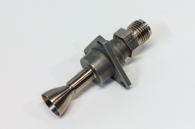
A project description will be added here later.
This project was a whitepaper design study that I did for myself to explore the potential of an ultra-high bypass turbofan engine with a hybrid combustion chamber. For this project, I did a full-up thermal cycle analysis, CAD modeled all the components, and completed a first pass structural analysis of the parts using hand calculations and static FEA.This was an interesting project for me because it was the first fully analyzed engine that I designed, and, because it was only a design study, I could choose to go with potentially expensive design features that I normally would not be able to pursue.
The intent of the design was to develop an engine that could be used at extremely high altitudes intermittently for station keeping or low-thrust primary propulsion. The combustion chamber assembly was designed to incorporate gaseous oxygen supplementation. The engine was a two-spooled engine with the inner spool mounted to the underside of the bypass duct. This layout would have allowed for easy core and combustion system modifications during the test program.
A project description will be added here later.
The design intent of this engine was to develop a simple turbofan upgrade that could be added to a basic turbojet core that I previously developed.
This engine was built on the gas-generator core of my previous kerosene centrifugal turbojet. I machined the aft fan out of a single alloy steel plate with a pressed in (and radially pinned) stainless steel inner turbine. The furthest aft fan bearing assembly was total-loss water cooled with a small amount of pressurized water.
Overall, the engine ran well and worked as a two-spool turbofan. At the end of testing, fan turbine thermal distortion caused the fan turbine and fan hub to separate causing fan imbalance.
During the build of the previous kerosene centrifugal turbojet, I built 2 or 3 of each part. This engine was assembled from the second set of parts.
The design intent of this engine was to improve on the kerosene centrifugal turbojet and evaluate the performance of a small ethanol can-annular chamber while experimenting with several different prototype turbine inlet nozzles. Overall engine performance was similar to the previous kerosene engine. This engine was my first can-annular engine.
This engine was a significant improvement on my first two turbojet engines. For this engine I designed and built custom compressor and turbine assemblies. The compressor wheel was sourced from a turbocharger, but I billet machined the compressor diffuser and compressor casing from scratch. The turbine was completely custom (I machined it from 304 stainless steel). It was the first axial turbine assembly and annular combustion chamber that I built. It was also my first engine where I CNC machined parts.
The engine only produced about 10 lb of thrust, but it was a great learning experience for future engines. The engine used a centrifugal compressor (with vaned dump diffuser), internal annular combustion chamber, axial turbine, and compressed air impingement starting.
The engine was started and warmed up using propane gas. Once running, the engine was transferred to 180 psi kerosene injection.
These two relatively simple turbocharger derived turbojets were the first two successful turbine engines that I designee and built. They both ran relatively well. At the time, the idea to making a turbojet from a turbocharger core was totally new and unique. I learned a lot from the development of these two engines. Both engines were small and produced only about 10-15 lbs of thrust.
Both engines used centrifugal compressors, single external can combustion chambers, annular inflow turbines, and compressed air impingement starting.
The first engine used low pressure fuel vaporizer tubes (40 psi diesel) and a total loss lubrication system. The second engine incorporated high pressure fuel injection (kerosene) and a semi-recirculating oil system. The biggest lessons that I learned were in cold starting sequence and fuel pressure variations from compressor back pressure.