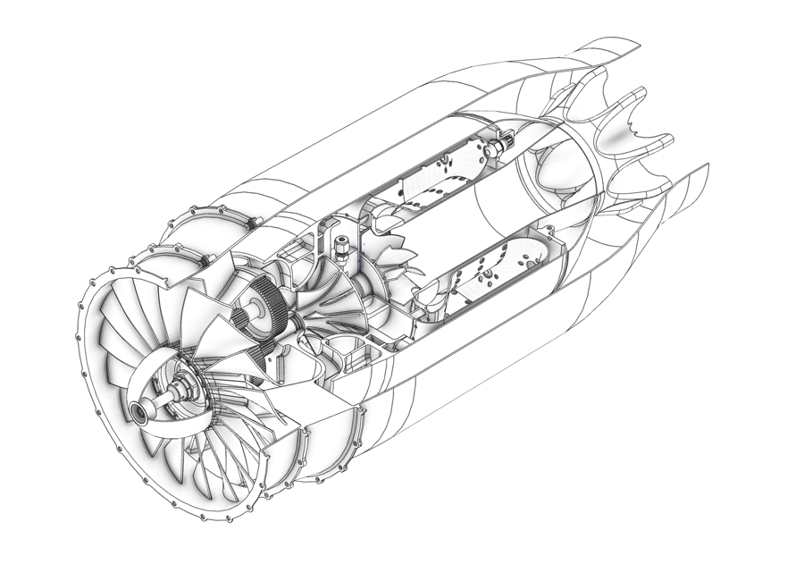
Ever since I made my first turbofan in 1996, I have been interested in the fuel efficiency benefits of turbofans. I have always enjoyed the simplicity of my turbojet engine designs, but their fuel economy is certainly a limiting factor in their performance. Over the years I have iterated a number of turbofan designs with the intent of making a small, fuel-efficient turbofan that could be applicable to general aviation or small aircraft use. I designed this engine to produce about 240 pounds of thrust while still maintaining a small diameter (around 9-inches overall). The fuel consumption would likely be in the 0.6-0.7 lbm/lbt/hr range. I plan to continue iterating subtle variations of this engine.
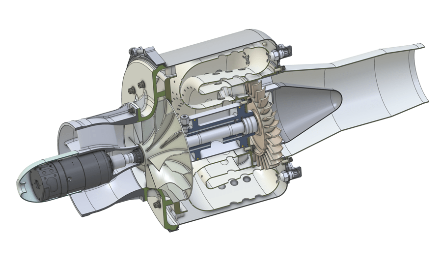
This was a quick design study that I did to flush out the details of a 200-pound thrust turbojet that I was designing in the background for several years. This engine incorporates a medium compression ratio centrifugal compressor and a reverse flow annular combustion chamber with high pressure fuel injection. The intent was to design an engine with a layout and packaging that could be practical for small aircraft applications. The engine has high pressure recirculating oil and an integrated starter generator in the nose.
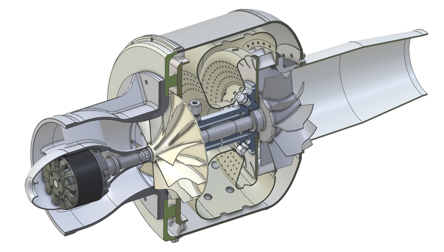
This is a small 110 lb thrust prototype turbojet engine design that I have been iterating on the side for some years. I recently decided that I’d give it a little more thought and attention. It’s in the same thrust range as my previous JA103 turbojet engine, but it is physically smaller and the deign details are a bit more refined. The design also takes advantage of new manufacturing methods that I did not have experience with during my previous JA103 build. At this time, I’m not sure if I will build this engine or not as I have several other engine designs in work.
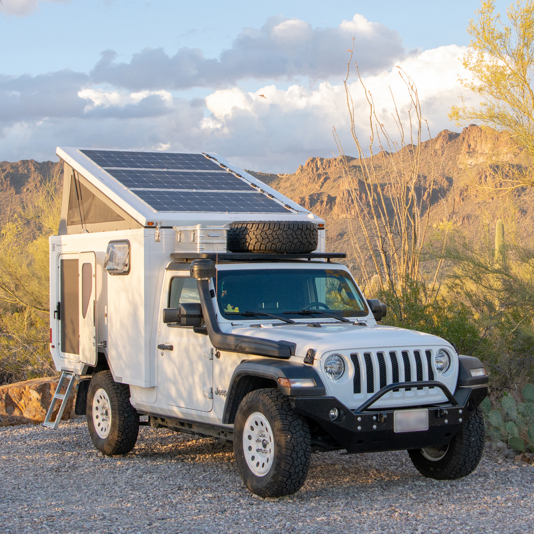
After we sold our Unimog, I wanted to design a smaller overland vehicle that had the same basic comforts of our Unimog habitat, but that would fit in a sea container for overseas shipping. After considering many chassis, I decided to design the camper around a modern Jeep JLU Wrangler. During the design phase, a professional traveler friend asked if I would make a copy of the camper for him, so I built two identical camper boxes, and he and I separately fitted out the chassis and camper interiors differently to suite our personal needs. I fabricated the camper shells predominantly from carbon fiber to meet my strict weight goals.
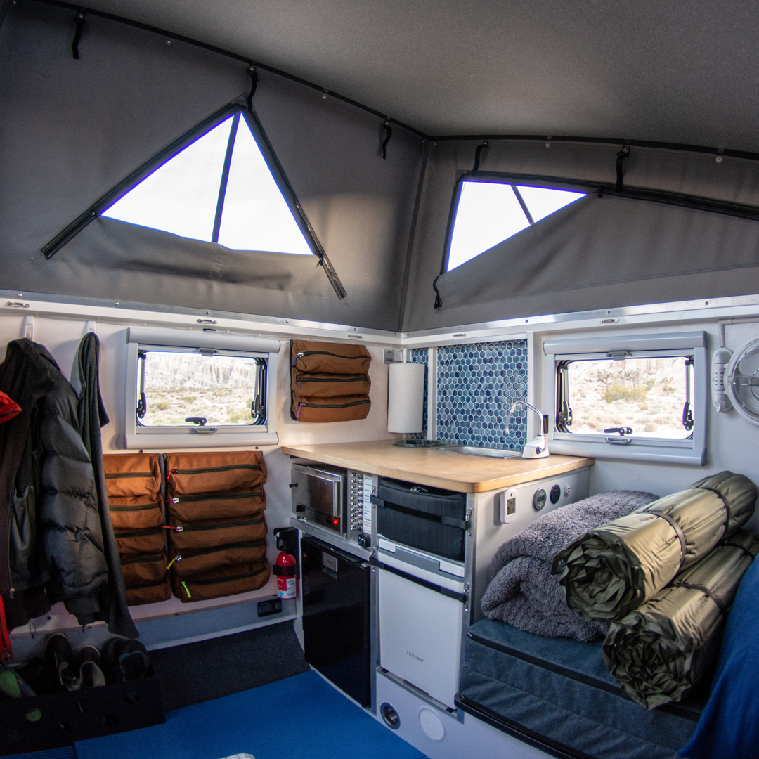
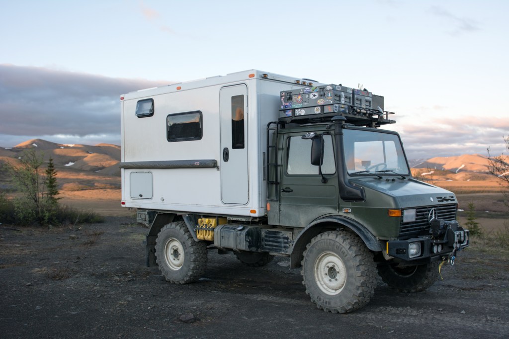
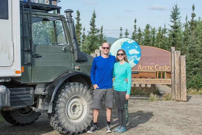
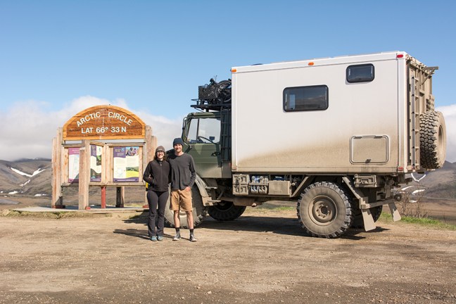
This was an expedition truck design and build project that I completed over an 18 month span with my wife Yvonne. The goal of the project was to build and travel in a custom four-wheel drive expedition truck. We took the vehicle on a 5 month trip to the arctic in 2019.
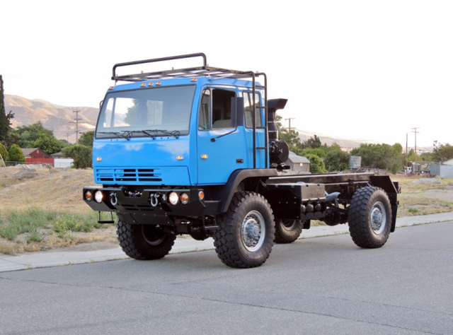
This was a joint project with my wife Yvonne. The goal of the project was to refurbish a surplus military LMTV for civilian use as a chassis for an expedition truck. At the completion of the refurbishment, we sold our freshly finished vehicle. A full description of the refurbishment can be found on our project blog: fuchsiafoxexpedition.wordpress.com.
This project was to design and build a one-off, stable/docile, open, two-place gyro with good visibility for fun local flying and short cross country flights. After flying different gyroplanes for comparison, and months of iterative design, I built the fuselage as a seamless carbon fiber shell molded over a removable CNC milled foam male tool. The gyro is now being finished by a gyro enthusiast in Oregon.
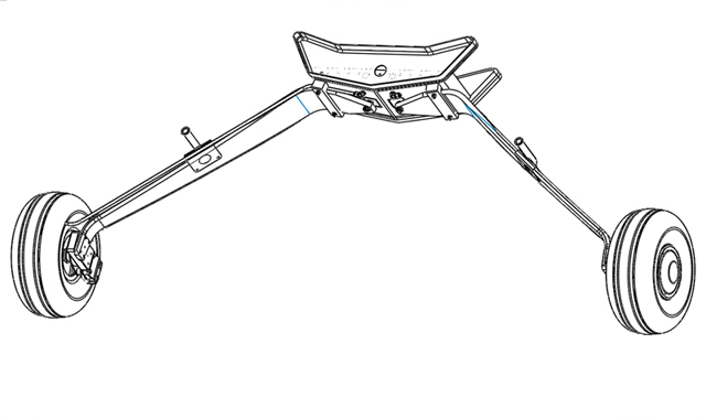
This project was the design of a spring steel landing gear for the tandem tractor gyroplane that I was concurrently developing at the time. The main landing gear were modified Cessna 140 landing gear legs. I used iterative Finite Element Analysis to tailor the leg spring stiffness to produce the desired deflection at max landing weight and landing descent rates. I milled the width of the gear legs down to the specific analyzed dimensions. The gear was sized per configuration applicable FAR23 load cases.
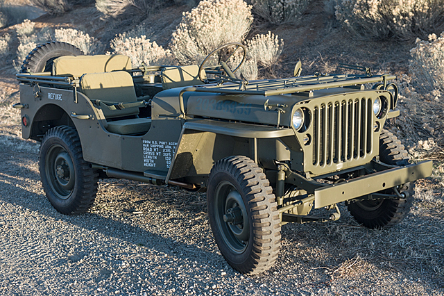
This was a complete restoration that I did of a 1943 Ford GPW WWII army jeep. This particular GPW was originally used by the US Army Corps of Engineers in Los Alamos, New Mexico during WWII on the Manhattan Project. I took every part down to clean metal and repainted with period correct paints. No body filler was used. I rebuilt or replaced every system component and returned the electrical system to its original 6 volts. The project took almost a year and a half of diligent work, but overall it was very satisfying to make every part clean, new, and historically correct.


")
")
")
")
")
")
")
")
")
")
")
")
")
